

Selasa, 26 Februari 2013
Kondisi Atmosferik dan Efisiensi Volumetrik
Kamis, 21 Februari 2013
Characteristic Operation....!!! kinematika Torak/Piston...!!!
Internal Combustion Engine atau diIndonesia dikenal dengan Motor Bakar memang sangat dibutuhkan sekali, bukan hanya menjadi alat untuk membantu aktivitas manusia tetapi juga sudah menjadi gaya hidup... contohnya ya buat balapan lhaa.... GASSPWOOLLL!!!
Piston/Torak yang bergerak pada Internal Combustion Engine mengalami yang namanya Gerak Torak/Piston...

Gambar diatas menunjukkan Gerak Torak Primer, Dimana Gerak Torak Primer adalah Gerak vertikal yg ditentukan oleh tinggi-rendahnya posisi sejumlah titik dari lingkaran engkol.

Gambar diatasini adalah diagram Gerak Torak Sekunder. Gerak Torak Sekunder sendiri adalah Gerak mendatar yang ditentukan dari penyimpangannya dari posisi horisontal.
Dalam sekali putaran poros engkol, batang penghubung berada dua kali pada kedudukan a dan d, dan empat kali pada kedudukan b dan c.
Rabu, 20 Februari 2013
Racing Leather on MotoGp.....!!!

Race leathers provide the first line of defence for competitors
in MotoGP when they suffer the occasional crashes and slides that all
riders go through. With corner speeds quicker than ever and lean angles
becoming increasingly acute the importance of a good set of leathers
cannot be underestimated.
The most common way a rider comes off his MotoGP bike is to lose
control of the front or rear tyre when leaning into a corner. This
usually results in the rider sliding along the asphalt and onto the
gravel at the side of the racetrack, sometimes apparently seamlessly,
though almost always at high speeds. Clearly doing this with exposed
flesh, normal clothing or inadequate leather protection would result in
massive damage to the skin and other parts of the body.
PROTECTION

The various manufacturers supplying the leathers to the MotoGP
participants therefore design the outfits to be as protective as
possible – but they must also be aerodynamic, breathable, comfortable,
durable, flexible, light and water resistant.
The MotoGP leather suits are mainly made of kangaroo leather,
which is more resistant, more flexible and weighs less than cow hide.
The leathers have to provide strong resistance and protection from
abrasion and impact in particularly vulnerable areas such as the back,
elbows and knees - whilst also giving the riders the elasticity they
need when utilizing their lightening quick reflexes.
Of course the riders’ leathers also have to work perfectly in
tandem with the helmets to stabilise the head, so the ‘humped’ back
protectors the race outfits carry fit snugly against the helmets
allowing air to glide over them aerodynamically when the riders are in
the customary hunched riding position. When stood upright and off their
racing machinery the back hump built into the back of the leathers can
clearly be seen, but they are also fairly flexible to allow movement and
bending of the back - in the right direction.
The built-in spinal column protection units and the chest
protectors the leathers also carry mainly use carbon, kevlar and
titanium combinations to safeguard the riders without weighing them
down. Indeed the overall weight of a Grand Prix rider’s leathers will of
course vary in relation to his physical stature, with the entire weight
of the leathers usually totalling around 3kg to 3.5kg
Selasa, 19 Februari 2013
MotoGP Basic...!!! Engines Explanation....!!!

DEFINITIONS

If 2-stroke engines proved more powerful than 4-strokes with similar engine capacities and similar rev counts, 4-strokes engines are more energy efficient and greener. This is because 4-strokes have a dedicated lubrication system, while 2-stroke engines burn a mixture of oil and gas.
As most manufacturers shifted their production towards bigger 4-stroke powered machines, the move to a 4-stroke prototype formula only seemed natural.
The key difference between the two types of engine lies in the combustion process: the four ‘strokes’ refer to the intake, compression, combustion and exhaust movements which occur during two crankshaft rotations per working cycle.
The 2-stroke internal combustion engine differs from the 4-stroke engine in that it completes the same four processes in only two strokes of the piston.
Single cylinder, two cylinder, four cylinder and six cylinder engines - While technical rules restrict the Moto3 World Championship to single cylinder engines and Moto2 to the Official Engine, MotoGP bikes were allowed from one to six cylinders or more up until 2012 when a limit of 4 cylinders with a maximum cylinder bore measurement of 81 mm was introduced.
According to the FIM rulebook, the number of cylinders dictates what the minimum accepted weight of the bike will be, and ballast may be added to achieve it. Due to unit cylinder performance and power-to-weight ratio, all the MotoGP manufacturers opted to use four cylinder engines even before the regulation was introduced.
However, those engines come in different forms, as some manufacturers, such as Ducati, Aprilia and Honda currently opt for V4 architecture, while Yamaha, BMW and Kawasaki have developed ‘inline four’ engines.
With V4’s the cylinders and pistons are aligned separately to each other, so that they take on a ‘V-shape’ from an angle looking along the crankshaft axis. This configuration decreases the total height, length and weight of the engine, in comparison with straight engine inline equivalents.
The choice of engine architecture has as much to do with design philosophy and the manufacturer’s heritage as with weight transfer and goals in terms of bike ‘rideability’.
Meanwhile, the terms 250cc(Moto3™), 600cc (Moto2™), 1000cc (MotoGP™) used to describe the three current categories in the World Championship simply refer to the ‘engine displacement’ or ‘cubic capacity’ of the respective machinery.
Senin, 18 Februari 2013
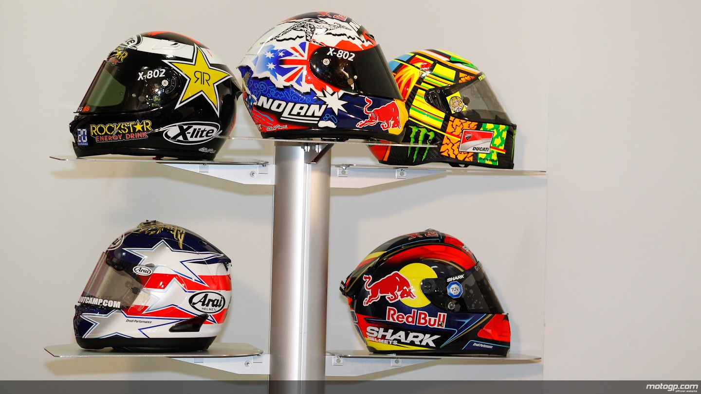
MotoGp Helmets Explanation.... Let's See...!!
It’s unthinkable that a MotoGP rider would be seen on track
without the most essential of safety items – a good crash helmet. MotoGP
helmets, along with the riders’ boots, leathers, gloves and reinforced
chest and spinal protection pads, are developed to the highest safety
standards with the latest technology.
In a sport where the participants reach speeds of more than 340
km/h, and crashes are a regular occurrence, reliable protective headgear
is of paramount importance for all World Championship competitors.
BASIC STRUCTURE

Racing helmets have the same basic structure as retail helmets
and the specific differences depend on the needs of the rider concerned
in terms of comfort, shape and size. Also, the internal accessories
required may differ, often depending on weather conditions.
For the helmet manufacturers, the MotoGP World Championship -
with its global media exposure to millions of fans - is a great way to
market their helmets, whilst the data they gather from the riders helps
them to improve the products they make available to the public.
Most riders have at least four helmets with them at each event,
with one being rain specific and modified to prevent ‘fogging’ or
‘misting’ and replacements always being required should the main helmet
become damaged.
COLOURFUL DESIGNS

In addition to protecting the lives of the riders, the helmets
they use have become the key element of the riders’ outfits through
which they can express themselves creatively. Many riders have
flamboyant helmet designs reflecting their personalities and tastes.
The distinctive colours and the clarity of the respective race
number or name of the rider on his helmet are essential for
identification by everyone from the race officials and teams to the
commentators and fans – the view otherwise blurred by the intensity and
speed of MotoGP’s busy race circuits.
Do you know MotoGP safety?? Grand Prix Safety Commision

As MotoGP bikes can reach top speeds of more than 340 km/h,
taking every step to protect the riders’ safety is of paramount
importance to everyone involved with motorcycle racing’s premier
competition.
In 2002, the FIM became concerned at the advances in design and engineering that resulted in higher speeds around the race track. For purposes of increasing safety, regulation changes related to weight, limits on fuel and engine capacity were introduced.
Senin, 04 Februari 2013
Chassis Explained
As you design a racing car, it is important that you know the
requirements of your engineering work. The nature of the race car's
normal operation and fatigue life depend on the structure and material
composition of the car. Therefore, topics such as metallurgy and
structural design are important for the designer to grasp. The whole
concept of engineering considerations is that you keep in mind four
aspects, where they are appropriate:
Any good chassis must do several things:

Contrary to some explanations, there is no such thing as a chassis that doesn't flex, but some are much stiffer than others. Even highly sophisticated Formula 1 chassis (actually, Formula 1 has monocoque structure) flex, and sometime some limited and controlled flexing is built in the car.
The range of chassis stiffness has varied greatly over the years. Basic chassis designs each have their own strengths and weaknesses. Every chassis is a compromise between weight, component size, complexity, vehicle intent, and ultimately, the cost. And even within a basic design method, strength and stiffness can vary significantly, depending on the details.
Any good chassis must do several things:
- Be structurally sound in every way over the expected life of the car and beyond. This means that nothing will ever break under normal conditions.
- Maintain the suspension mounting locations so that handling is safe and consistent under high cornering and bump loads. This means that there is no flexing of the body, or at least to reduce flexing on lowest possible value.
- Support the body panels and other components so that everything feels solid and has a reliable life span.
- Protect the driver from external intrusion.
Contrary to some explanations, there is no such thing as a chassis that doesn't flex, but some are much stiffer than others. Even highly sophisticated Formula 1 chassis (actually, Formula 1 has monocoque structure) flex, and sometime some limited and controlled flexing is built in the car.
The range of chassis stiffness has varied greatly over the years. Basic chassis designs each have their own strengths and weaknesses. Every chassis is a compromise between weight, component size, complexity, vehicle intent, and ultimately, the cost. And even within a basic design method, strength and stiffness can vary significantly, depending on the details.
Minggu, 03 Februari 2013
Can E15 Gasoline Really Damage Your Engine?
Automakers have filed a lawsuit against the EPA's decision to make
E15 (gasoline with 15 percent alcohol) legal for all cars after 2007.
They argue that, among other problems, the blend could damage the
engine. Wait, moonshiners used to run their cars on 190-proof hooch. Can
ethanol really do damage to an engine? Yes. Here's how.
 Most people realize that all of us
burn gasohol—a mixture of gasoline and alcohol—in our
cars. Just about every gallon of gas pumped today contains as much as 10
percent domestically produced ethanol. Gummed-up fuel systems, damaged
tanks
and phase separation caused by stray moisture infiltrating fuel systems
have plagued many consumers since this mixture debuted, and the problems
will
only get worse if government policy to increase the proportion of
ethanol to gasoline is implemented. Don't get me wrong: Gasoline diluted
with ethanol is a perfectly acceptable motor fuel when it's stored
properly, dispensed promptly and burned in vehicles and power equipment
designed to handle it. Which, unfortunately, is not always the case.
Most people realize that all of us
burn gasohol—a mixture of gasoline and alcohol—in our
cars. Just about every gallon of gas pumped today contains as much as 10
percent domestically produced ethanol. Gummed-up fuel systems, damaged
tanks
and phase separation caused by stray moisture infiltrating fuel systems
have plagued many consumers since this mixture debuted, and the problems
will
only get worse if government policy to increase the proportion of
ethanol to gasoline is implemented. Don't get me wrong: Gasoline diluted
with ethanol is a perfectly acceptable motor fuel when it's stored
properly, dispensed promptly and burned in vehicles and power equipment
designed to handle it. Which, unfortunately, is not always the case.
Jumat, 01 Februari 2013
Formula One Engines
Although F1 racing engines have lost some of the attractiveness they
used to have when the regulations allowed more freedom, every single
design currently in use is still a highly advanced piece of engineering
that has required lots of time and thought. An engine is the only power
source of a Formula One car - apart from the KERS systems in 2009 which
are indirectly charged by the power generated by the engine - and is a
structural part of the chassis.
 Because
of the regulations and engineering optimisations, all curent engines
are of a similar type, and feature the following similarities:
Because
of the regulations and engineering optimisations, all curent engines
are of a similar type, and feature the following similarities:
Back in 1997, Ford Cosworth started a furious battle for weight reduction as their CR1 at the time was at least 25kg lighter than any other. Although they
suffered some reliability problems troughout the season, the engine was an example
for the others, as it allowed the team to shift ballast in the car to benefit the car's handling.
Although they
suffered some reliability problems troughout the season, the engine was an example
for the others, as it allowed the team to shift ballast in the car to benefit the car's handling.
As a reaction to this weight shedding, the the 1998 Mercedes-benz engine was possibly one of the most revolutionary engines ever built, making performance gains and drastic weight cuts at the same time. It quickly proved good enough to be the basis of Mika Hakkinen's two consecutive world titles with McLaren Mercedes. When in 2000, the FIA decided to limit the use of Berillium alloys - to a maximum of 5 mass percentage - due to being poisonous in high quantities, Mercedes struggled for years to recover from that setback - they could not match anymore the power of the at that time mighty Ferrari and BMW engines.

 By the end of 2005, most of the teams had converged their designs to 3
litre V10's with an internal angle of 90°. The teams' designers had
come to the conclusion that 90° was the best compromise between
performance and stiffness of the engine itself.
By the end of 2005, most of the teams had converged their designs to 3
litre V10's with an internal angle of 90°. The teams' designers had
come to the conclusion that 90° was the best compromise between
performance and stiffness of the engine itself.
That same year, some 3l V10 engines were producing more than 980hp and running very close to the 1000hp mark, a figure that was never reached since the ban on turbo engines. It was a sign for F1's governing body to change the regulations as top speeds at Monza of 370km/h were deemed hazardous for the drivers as well as the spectators. The maximum capacity was thus reduced to 2.4l and the cylinder count to 8. Additionally, the FIA ruled that an engine freeze would come into effect a year later to put an end to the spending race.
Only 2 years later however, halfway through 2008, the FIA and several teams who strictly followed the rules - including the likes of Toyota and Renault - found that the regulations still allowed too much freedom. It appeared that over the last year, Mercedes and Ferrari had been able to add up to 40hp to their engines as so called "reliability updates", while others had followed the engine freeze more strictly. Several meetings with FIA officials and the teams' principals then resulted in an equalisation of the engines, in which the less powerful could put on several updates to be on par in the next years.
Even so, without fiercely looking for improvements, a current F1 engine is a highly interesting piece of engineering, in total consisting of 5000 seperate parts, 1500 of which are moving. It is estimated that when in operation, a new F1 engine can produce around 720hp, but would be able to reach up to 780hp and above 20,000rpm if there would not be a limit on engine revolutions.
Another deciding point trying to reach a maximum of power out of an engine is the exhaust. The minor change of lenght or form of an exhaust can influence the horsepowers drastically. Although variable outlet systems are not allowed, the exhaust system on a race car does not feature a muffler, lacks a katalysator and is specially made to whitstand temperatures as high as 1200°C, a lot more than what is achieved with a regular road engine.
Contrary to boxer or flat engines, V-angled combustion engines pose an extra design problem, as it is crucial for an engine's performance that the V-angle is chosen wisely. This angle important to ensure a correct firing sequence and hence also influences its primary balance.
Calculating possible V angles for a specific number of cylinders is fortunately not a daunting task. If you consider that every combustion cycle takes 2 turns - intake and combustion phase - of the crankshaft, and a full circle is 360°, the engine's included V-angle x the number of cylinders must be a function of 720 in order to achieve evenly spaced cylinder firing and primary balance.
That is also why a boxer engine is an ideal layout. The cylinders are opposed at 180° so having 2 or 4 or 6 or 8 or 10 or 12 isn't that big. Perfect primary balance is easy to achieve, as long as the reciprocating and rotating parts are in balance and, the firing order is always evenly spaced. A few examples make it clear why several specific angles have been very popular in F1 engine design:
However, due to the space restrictions and aerodynamic requirements of a race car, the positioning of these components is completely different. The following shows the internals of a championship winning Renault R25 of 2005, included with its Renault RS25 engine (2). The flat panels located nearly vertically in the front of the side pods are the radiators (4). While in this picture the radiator is covered with a protective hose, it is not during running as air passes through the aluminium fins of the radiator. Their position however varies considerably in different cars as they are influenced by the aerodynamic and weight distribution requirements of a car.
 Contrary to popular belief, the air inlet above the driver's head is
not part of the cooling system but instead provided the engine's
cylinders with air to be mixed with fuel for combustion. It is commonly
thought that the purpose of this is to 'ram' air into
the engine like a supercharger, but the airbox does
the opposite.
The carbon fibre duct (1) gradually
widens out as it approaches the engine, effectively creating a venturi
and a suction effect on the small air inlet. The shape of this ducts
and inlet however must be carefullly designed to both fill
all cylinders equally and not harm the exterior aerodynaimcs of the
engine cover,
all to optimize the volumetric efficiency.
Contrary to popular belief, the air inlet above the driver's head is
not part of the cooling system but instead provided the engine's
cylinders with air to be mixed with fuel for combustion. It is commonly
thought that the purpose of this is to 'ram' air into
the engine like a supercharger, but the airbox does
the opposite.
The carbon fibre duct (1) gradually
widens out as it approaches the engine, effectively creating a venturi
and a suction effect on the small air inlet. The shape of this ducts
and inlet however must be carefullly designed to both fill
all cylinders equally and not harm the exterior aerodynaimcs of the
engine cover,
all to optimize the volumetric efficiency.
Marked with (3) is the engine exhaust system while (5) and (6) identify the rear suspension that is fitted onto the gearbox.
Facts and figures
Because
of the regulations and engineering optimisations, all curent engines
are of a similar type, and feature the following similarities:- All F1 engines are naturally aspirated V8's of 2400cc
- Engines are limited to 18,000rpm
- The weight is exactly 95kg (each manufacturer easily reaches this regulated minimum weight)
- Engine blocks are constructed of forged aluminium alloy, because of the weight advantages it gives in comparison to steel. Other materials would maybe give some extra advantages, but to limit costs, the FIA has forbidden all non-ferro materials.
- Crankshaft and piston rods are Iron based for strength.
- At its maximum pace the current V8 engines consume around 60 litres of petrol for 100km of racing.
- It's not exactly known how much oil such a top engine contains, but this oil is for 70% in the engine, while the other 30% is in a dry-sump lubrication system that changes oil within the engine three to four times a minute.
- Before its first track time and after each race, each engine is tested on an engine dyno to validate its performance and identify problems. A videoclip of Renault's RS24 on the dyno can be found here.
Evolution of engine design
All current engines run by the competing F1 teams are very similar due to the very stringent regulations that have increasingly come into play since 2006. Until that time, all car manufacturers involved in F1 were effectively outracing each other in a spending race. It is not a lie to claim that in the years after 1995, the manufacturer who invested most and could hire most people could produce the best engine.Back in 1997, Ford Cosworth started a furious battle for weight reduction as their CR1 at the time was at least 25kg lighter than any other.
Although they
suffered some reliability problems troughout the season, the engine was an example
for the others, as it allowed the team to shift ballast in the car to benefit the car's handling.As a reaction to this weight shedding, the the 1998 Mercedes-benz engine was possibly one of the most revolutionary engines ever built, making performance gains and drastic weight cuts at the same time. It quickly proved good enough to be the basis of Mika Hakkinen's two consecutive world titles with McLaren Mercedes. When in 2000, the FIA decided to limit the use of Berillium alloys - to a maximum of 5 mass percentage - due to being poisonous in high quantities, Mercedes struggled for years to recover from that setback - they could not match anymore the power of the at that time mighty Ferrari and BMW engines.
That same year, some 3l V10 engines were producing more than 980hp and running very close to the 1000hp mark, a figure that was never reached since the ban on turbo engines. It was a sign for F1's governing body to change the regulations as top speeds at Monza of 370km/h were deemed hazardous for the drivers as well as the spectators. The maximum capacity was thus reduced to 2.4l and the cylinder count to 8. Additionally, the FIA ruled that an engine freeze would come into effect a year later to put an end to the spending race.
Only 2 years later however, halfway through 2008, the FIA and several teams who strictly followed the rules - including the likes of Toyota and Renault - found that the regulations still allowed too much freedom. It appeared that over the last year, Mercedes and Ferrari had been able to add up to 40hp to their engines as so called "reliability updates", while others had followed the engine freeze more strictly. Several meetings with FIA officials and the teams' principals then resulted in an equalisation of the engines, in which the less powerful could put on several updates to be on par in the next years.
Even so, without fiercely looking for improvements, a current F1 engine is a highly interesting piece of engineering, in total consisting of 5000 seperate parts, 1500 of which are moving. It is estimated that when in operation, a new F1 engine can produce around 720hp, but would be able to reach up to 780hp and above 20,000rpm if there would not be a limit on engine revolutions.
Difference with road engines
- Higher volumetric efficiency. VE is used to describe the amount of fuel/air in the cylinder in relation to regular atmospheric air. If the cylinder is filled with fuel/air at atmospheric pressure, then the engine is said to have 100% volumetric efficiency. Turbo chargers for instance can increase VE to above 100% while normally aspirated engines tipically run anywhere between 80% and 100%. In this region however, a Formula One engine usually can achieve a higher VE than normal road engines because of their highly optimised intake manifolds.
- Unfortunately, from the total fuel energy that is put into the cylinders, averagely less than 1/3 ends up as useable horsepower. Ignition timing, thermal coatings, plug location and chamber design all affect the thermal efficiency (TE). Low compression street engines may have a TE of approximately 0.26, a racing engine may reach approximately 0.34. This seemingly small difference results in a difference of about 30% (0.34 - 0.26 / 0.26) more horsepower than before.
- From all that power generated, part of it is used by the engine to run itself. The left over power is what you would measure on a dynamometer. The difference between what you would measure on the dyno and the workable power in the cylinder is the mechanical efficiency (ME). Mechanical efficiency is affected by rocker friction, bearing friction, piston skirt area, and other moving parts, but it is also dependent on the engine's RPM. The greater the RPM, the more power it takes to turn the engine. This means limiting internal engine friction can generate a large surplus in power output, and where in F1 the stress is on power, on the road it is also on fuel consumption.
Another deciding point trying to reach a maximum of power out of an engine is the exhaust. The minor change of lenght or form of an exhaust can influence the horsepowers drastically. Although variable outlet systems are not allowed, the exhaust system on a race car does not feature a muffler, lacks a katalysator and is specially made to whitstand temperatures as high as 1200°C, a lot more than what is achieved with a regular road engine.
Engine design phylosophies
Considering internal combustion engines (thus leaving out oscillating and Wankel rotary combustion engines), there are basically three different ways of building an engine. The difference here is how the cylinders are placed compared to each other.- Inline engines, where all cylinders are placed next to (or after) each other are not used in Formula One since the 60's. While the engines are small, they are long and therefore require a heavy cranckshaft.
- Boxer engines are actually one of the best ways to build an engine, if all external factors allow it. Two cylinder rows are placed opposed to each other. You could consider a boxer engine as being a 180° V-angle engine design. These engines became popular in F1 because of the low centre of gravity and the average production costs, but later on disappeared out of the picture as this type of engine is not sufficiently stiff enough to whitstand the car's G-forces in cornering conditions. Ferrari for instance have run 12 cylinder boxer engines from 1970 to 1980 before moving to a 120° V-angle engine.
- V-type engines, as currently used in all F1 cars. The V is in fact the geometrical angle that seperated the two cylinder banks from each other where the crankshaft can be considered the origin of the angle. Obviously for this type of engine the size of the V is a major factor and must be decided in the first phases of the engine design. Previously, engines have been designed with angles such as 60° V12 or 72° V10. Although it has historically been an interesting evolution to see the differences between the teams' engines, the FIA have fixed the engine type to 90° V8 models.
Contrary to boxer or flat engines, V-angled combustion engines pose an extra design problem, as it is crucial for an engine's performance that the V-angle is chosen wisely. This angle important to ensure a correct firing sequence and hence also influences its primary balance.
Calculating possible V angles for a specific number of cylinders is fortunately not a daunting task. If you consider that every combustion cycle takes 2 turns - intake and combustion phase - of the crankshaft, and a full circle is 360°, the engine's included V-angle x the number of cylinders must be a function of 720 in order to achieve evenly spaced cylinder firing and primary balance.
That is also why a boxer engine is an ideal layout. The cylinders are opposed at 180° so having 2 or 4 or 6 or 8 or 10 or 12 isn't that big. Perfect primary balance is easy to achieve, as long as the reciprocating and rotating parts are in balance and, the firing order is always evenly spaced. A few examples make it clear why several specific angles have been very popular in F1 engine design:
- As mentioned earlier, Ferrari have used a 60° V12 or 120° V12 engine. As for the first option, divide 720° by 12 cylinders and you get 60. You get 120° when you imagine a V12 as two aligned V6 engines.
- Renault's extremely successful 72° V10 engines share the same thoughts. It is the perfect bank angle for any V10 engine if a boxer is not an option. One cylinder is fired every time the cranckshaft has completed 72° so that after 2 turns every single piston has gone through one complete cycle.
- Currently every team runs 90° V8 engines but not only because the regulations prescribe so. Also this is a perfect angle and meets the size requirements set by the aerodynamicists.
Contrary to these optimal choices, there have also been unusual uses. For instance the 2005 90° V10 engines that everyone but Renault were using. While they may have been more interesting for other reasons, it's performance could theoretically not beat Renault's RS25 that was a 72° V10. The 90° V10 engines hence had either offset crankpins or a funny firing order.
- Before their RS24 Renault was trying a revolutionary design as they designed a 112° V10. Although the engine evolved from RS21 to RS23 and was beneficial in terms of the centre of gravity it was finally abandoned. The engine could not reach competitively high rpms since the uneven firing order introduced unwanted vibrations in the engine.
Cranckshaft design
Although the V8 with the now compulsory cylinder angle of 90 degrees may look like a sawn-off V10, technically it is an entirely separate concept with its own specific requirements. The V8 has a distinct firing sequence and demands a fundamentally different crankshaft design. Whereas a 72-degree offset crankshaft was used in most V10 Formula One engines, V8 powerplants can feature crankshafts with either four throws spaced at 90 degrees or four throws spaced at 180 degrees. Standard production engines are fitted with 90-degree crankshaft variants due to their better dynamic attributes, but a 180-degree crankshaft is favoured in racing car engine design. The improved performance this allows offsets the disadvantages in terms of dynamics.Cooling
With such a low thermal efficiency, cooling of any internal combustion engine is vital for its correct operation. Basically, an F1 cooling system is the same as in any regular road car, as engine cooland and oil is pumped through a radiator to cool down before completing another cycle through the engine.However, due to the space restrictions and aerodynamic requirements of a race car, the positioning of these components is completely different. The following shows the internals of a championship winning Renault R25 of 2005, included with its Renault RS25 engine (2). The flat panels located nearly vertically in the front of the side pods are the radiators (4). While in this picture the radiator is covered with a protective hose, it is not during running as air passes through the aluminium fins of the radiator. Their position however varies considerably in different cars as they are influenced by the aerodynamic and weight distribution requirements of a car.
Marked with (3) is the engine exhaust system while (5) and (6) identify the rear suspension that is fitted onto the gearbox.
Transmission
The transmission of any car is considered to be all intermediate gears and systems to get the engine rotational power to the wheels. In reality this comes down to the gearbox and differential, which are both assembled into the gearbox casing. Just as with the engine, this casing - often made of titanium or carbon fibre - is also a structural part of the chassis and is firmly bolted onto the rear end of the engine. More can be found in the specific article about F1 transmissions.Regulations
The current regulations on Formula One engines can be summarised as follows. These specifications have become more strict during recent years in an attempt to limit costs and decrease performance. You can find an evolution of the most important regulations per era in the safety section. As this is only an exerpt of the most important regulations on engines, you would need to see the official FIA technical regulations before you start to design a Formula One engine yourself.
Specification
Only 4-stroke engines with reciprocating pistons are permitted.
Engine capacity must not exceed 2400 cc.
Crankshaft rotational speed must not exceed 18,000rpm.
Supercharging is forbidden.
All engines must have 8 cylinders arranged in a 90º “V” configuration and the normal section of each cylinder must be circular.
Engines must have two inlet and two exhaust valves per cylinder.
Only reciprocating poppet valves are permitted.
The sealing interface between the moving valve component and the stationary engine component must be circular.
Dimensions, weight and centre of gravity
Cylinder bore diameter may not exceed 98mm.
Cylinder spacing must be fixed at 106.5mm (+/- 0.2mm).
The crankshaft centreline must not be less than 58mm above the reference plane.
The overall weight of the engine must be a minimum of 95kg.
The centre of gravity of the engine may not lie less than 165mm above the reference plane.
The longitudinal and lateral position of the centre of gravity of the engine must fall within a region that is the geometric centre of the engine, +/- 50mm. The geometric centre of the engine in a lateral sense will be considered to lie on the centre of the crankshaft and at the mid point between the centres of the forward and rear most cylinder bores longitudinally.
Variable geometry systems are not permitted
Materials
Magnesium based alloys, Metal Matrix Composites (MMC’s) and Intermetallic materials may not be used anywhere in an engine
Coatings are free provided the total coating thickness does not exceed 25% of the section thickness of the underlying base material in all axes. In all cases the relevant coating must not exceed 0.8mm.
Pistons must be manufactured from an aluminium alloy which is either Al-Si ; Al-Cu ; Al-Mg or Al-Zn based.
Piston pins, crankshafts and camshafts must be manufactured from an iron based alloy and must be machined from a single piece of material.
A supplementary device temporarily connected to the car may be used to start the engine both on the grid and in the pits.
source: http://www.f1technical.net/articles/4
Aerodynamics in racing
Aerodynamics is the science that studies objects moving through air. It is closely
related to fluid dynamics as air is considered a compressible fluid. Nowadays, aerodynamics
is the utmost important factor in Formula One car performance. It has even nearly become
one of the only aspects of performance gain due to the very marginal gains that can currently
be made by engine changes or other mechanic component development. This downforce
can be likened to a "virtual" increase in weight, pressing the car
down onto the road and increasing the available frictional force between the
car and the road, therefore enabling higher cornering speeds.

Furthermore, as Formula One teams have the greatest resources to develop aero efficiency of its cars, the greatest strives are made here. F1 teams have unrivalled CFD computing power and at least one full time wing tunnel, only for validating and improving their designs.
While basic aerodynamic methods and formulas can be simply resolved, other properties are verifiable with empirical formulas. More complex shapes such as airplanes or racing cars are however impossible to calculate precisely, rendering computational fluid dynamic systems (CFD applications on super computers) and wind tunnels an absolute requirement to validate designs
From a spectator's point of view, a car can be considered in (at least) 3 parts: the front wing, the car's body and the rear wing. Each of the parts can be optimised for the required downforce at a minimum of drag. Practically however, every component has its influence on the behaviour of the car and cannot be regarded as an individual component. As a result, no element is tested individually, but always a complete scale model of a car.
Because a complete racing car is a very complex system, teams of engineers usually evolve the car step by step, developing a particular item and check its effect on the car. Such overall effect can then be calculated with "Amdahl's law":

Here is the fraction of the system (when this fraction generates
5% of the car's drag, then is 0.05) that can be improved,
the fraction of the system (when this fraction generates
5% of the car's drag, then is 0.05) that can be improved,  is the improvement factor on this fraction (division of the drag in Newtons
and the new drag force after improving that element), and
is the improvement factor on this fraction (division of the drag in Newtons
and the new drag force after improving that element), and  is the overall improvement that will be achieved.
After verifying its improvement, the car's efficiency is determined and then simulated on different tracks to see on where it is useful. That usefulness is always the result of a reduction in drag or an increase in downforce.
 Drag comes in various forms, one of them being friction drag which is the result of
the friction of the solid molecules against air molecules in their neighbourhood. Friction
and its drag depend on both the fluid and the solid properties. A smooth surface of
the solid for example produces less skin friction compared to a rough one. For the
fluid, the friction varies along with its viscosity and the relative magnitude of the
viscous forces to the motion of the flow, expressed as the Reynolds number. Along the
solid surface, a boundary layer of low energy flow is generated and the magnitude of
the skin friction depends on conditions in the boundary layer.
Drag comes in various forms, one of them being friction drag which is the result of
the friction of the solid molecules against air molecules in their neighbourhood. Friction
and its drag depend on both the fluid and the solid properties. A smooth surface of
the solid for example produces less skin friction compared to a rough one. For the
fluid, the friction varies along with its viscosity and the relative magnitude of the
viscous forces to the motion of the flow, expressed as the Reynolds number. Along the
solid surface, a boundary layer of low energy flow is generated and the magnitude of
the skin friction depends on conditions in the boundary layer.
Additionally, drag is a form of resistance from the air against the solid moving object. This form of drag is dependent on the particular shape of a wing, and is therefore called form drag. As air flows around a body, the local velocity and pressure are changed, effectively creating a force.
Interference drag or induced drag on the other hand is the result of vortices that are generated behind the solid object. Due to the change of direction of air around the wing, a vortex is created where the airflow meets unchanged, straight flow. The size of the vortex, and thereby its drag strength increases with an increasing angle of attack of the aerofoil. As a primary source of possible drag reduction, Formula One teams try to counteract this drag by adding end plates to wings or with fillets at the suspension arms.
Other sources of drag include wave drag and ram drag. The first is unimportant for normal racecars as it occurs when the moving object speeds up to the speed of sound. Ram drag on the other hand is the result of slowing down the free airstream, as in an air inlet.
The amount of drag that a certain object generates in an airflow is quantified in a drag coëfficient. This coëfficient expresses the ratio of the drag force to the force produced by the dynamic pressure times the area. Therefore, a of 1 denotes
that all air flowing onto the object will be stopped, while a theoretical 0 is a perfectly
clean air stream.
of 1 denotes
that all air flowing onto the object will be stopped, while a theoretical 0 is a perfectly
clean air stream.
At relatively high speeds, ie. at high Reynolds number ( ),
the aerodynamic drag force can be calculated by this formula:
),
the aerodynamic drag force can be calculated by this formula:

where is the force of drag (in Newton),
  the density of the air,
 the speed of the object relative to the fluid (in m/s),
  the reference
surface and the coëfficient of
drag. Note the minus sign and the vector
the reference
surface and the coëfficient of
drag. Note the minus sign and the vector  which indicate that
the resulting drag force is opposite to the movement of the object.
which indicate that
the resulting drag force is opposite to the movement of the object.
The evolution of aerofoils to what they are now is mainly thanks to the genious and research of a few well known scientists. In 1686, Sir Isaac Newton presented his three laws of motion, one of them being the conservation of energy. He stated that energy is constant in a closed system, although it can be converted from one type to another. Out of that theory, Daniel Bernouilli deducted a formula proving that the total energy in a steadily flowing fluid system is a constant along the flow path. An increase in the fluid’s speed must therefore be matched by a decrease in its pressure. Adding up the pressure variation times the area around the entire body determines the aerodynamic force on the body.
An aerofoil's operation can be easily explained when you consider a wing in a steady, laminar flow of air. As air is a gas, its molecules are free to move around and may have a different speed at different locations in the airstream. As downforce generating aerofoils are mostly designed with more thickness on the lower side, the lower airstream is slightly reduced in surface, hence increasing the flow speed and decreasing the pressure. On top of the wing, the airspeed is lower, and thus the pressure difference will generate a downward force on the wing. Additionally, and in line with Newton's third law of motion, downforce wings are never straight and induce a new turning of the airflow. More specifically, the shape of the wing will turn air upwards and change its velocity. Such speed creates a net force on the body.

This shows that a force causes a change in velocity
  , or also, a change
in velocity generates a force. Note that a velocity is a vectorial unit, having a speed
and a direction component. So, to change of either of these components, you must impose
a force. And if either the speed or the direction of a flow is changed, a force is generated.
, or also, a change
in velocity generates a force. Note that a velocity is a vectorial unit, having a speed
and a direction component. So, to change of either of these components, you must impose
a force. And if either the speed or the direction of a flow is changed, a force is generated.
It is very important to note that the turning of the fluid occurs because the molecules of the fluid stay in contact with the solid body since the molecules are free to move. Any part of the solid body can deflect a flow. Parts facing the oncoming flow are said to be windward, and parts facing away from the flow are said to be leeward. Both windward and leeward parts deflect a flow. Ignoring the leeward deflection leads to the incorrent "skipping stone" theory of lift.
You can simulate airflow around a simple aerofoil with NASA's Foilsim II.
Downforce is however often explained by the "equal transit time" or "longer path" theory, stating that particles that split ahead of the aerofoil will join together behind it. In reality however, the air on the longer side of the wing will flow much faster, further increasing the downforce effect.
While these simplified versions are the basics of lift and downforce generation, the reality can hardly be simplified and is a complex study, requiring high power computer systems. For a gas, we have to simultaneously conserve the mass, momentum, and energy in the flow. Hence, a change in the velocity of a gas in one direction results in a change in the velocity of the gas in a direction perpendicular to the original change. The simultaneous conservation of mass, momentum, and energy of a fluid (while neglecting the effects of air viscosity) are called the Euler Equations after Leonard Euler. Several computer algorithms are based on these equations to make an approximation of the real situation.
Because of the complexity, today's Formula One cars are designed with CFD (computational fluid dynamics) and CAD (computer aided design) that allows engineers to design a car, and immediately simulate the airflow around it, incorporating environmental parameters like traction, wind speed and direction, and much more.
By Steven De Groote
Source: http://www.f1technical.net/articles/10
Furthermore, as Formula One teams have the greatest resources to develop aero efficiency of its cars, the greatest strives are made here. F1 teams have unrivalled CFD computing power and at least one full time wing tunnel, only for validating and improving their designs.
While basic aerodynamic methods and formulas can be simply resolved, other properties are verifiable with empirical formulas. More complex shapes such as airplanes or racing cars are however impossible to calculate precisely, rendering computational fluid dynamic systems (CFD applications on super computers) and wind tunnels an absolute requirement to validate designs
Application in Formula One
F1 (and in general, all winged racing cars) can be considered to be canard configurations in the sense that the front and back wings are on opposite sides of the centre of gravity and both are "lifting" (strongly) in the same direction, in this case creating downforce.From a spectator's point of view, a car can be considered in (at least) 3 parts: the front wing, the car's body and the rear wing. Each of the parts can be optimised for the required downforce at a minimum of drag. Practically however, every component has its influence on the behaviour of the car and cannot be regarded as an individual component. As a result, no element is tested individually, but always a complete scale model of a car.
Because a complete racing car is a very complex system, teams of engineers usually evolve the car step by step, developing a particular item and check its effect on the car. Such overall effect can then be calculated with "Amdahl's law":
Here is
the fraction of the system (when this fraction generates
5% of the car's drag, then is 0.05) that can be improved,
is the improvement factor on this fraction (division of the drag in Newtons
and the new drag force after improving that element), and
is the overall improvement that will be achieved.After verifying its improvement, the car's efficiency is determined and then simulated on different tracks to see on where it is useful. That usefulness is always the result of a reduction in drag or an increase in downforce.
Drag
Drag is the aerodynamic force that is opposite to the velocity of an object moving through air (or any other fluid). Its size is proportional to the speed differential between the air and the solid object. It is therefore unimportant if either the air is moving around a static object or if the object is moving at a speed through static air.Drag comes in various forms, one of them being friction drag which is the result of
the friction of the solid molecules against air molecules in their neighbourhood. Friction
and its drag depend on both the fluid and the solid properties. A smooth surface of
the solid for example produces less skin friction compared to a rough one. For the
fluid, the friction varies along with its viscosity and the relative magnitude of the
viscous forces to the motion of the flow, expressed as the Reynolds number. Along the
solid surface, a boundary layer of low energy flow is generated and the magnitude of
the skin friction depends on conditions in the boundary layer.Additionally, drag is a form of resistance from the air against the solid moving object. This form of drag is dependent on the particular shape of a wing, and is therefore called form drag. As air flows around a body, the local velocity and pressure are changed, effectively creating a force.
Interference drag or induced drag on the other hand is the result of vortices that are generated behind the solid object. Due to the change of direction of air around the wing, a vortex is created where the airflow meets unchanged, straight flow. The size of the vortex, and thereby its drag strength increases with an increasing angle of attack of the aerofoil. As a primary source of possible drag reduction, Formula One teams try to counteract this drag by adding end plates to wings or with fillets at the suspension arms.
Other sources of drag include wave drag and ram drag. The first is unimportant for normal racecars as it occurs when the moving object speeds up to the speed of sound. Ram drag on the other hand is the result of slowing down the free airstream, as in an air inlet.
The amount of drag that a certain object generates in an airflow is quantified in a drag coëfficient. This coëfficient expresses the ratio of the drag force to the force produced by the dynamic pressure times the area. Therefore, a
of 1 denotes
that all air flowing onto the object will be stopped, while a theoretical 0 is a perfectly
clean air stream.At relatively high speeds, ie. at high Reynolds number (
),
the aerodynamic drag force can be calculated by this formula:where
is the force of drag (in Newton), the density of the air,
the speed of the object relative to the fluid (in m/s), the reference
surface and the coëfficient of
drag. Note the minus sign and the vector which indicate that
the resulting drag force is opposite to the movement of the object.Downforce
Aerofoils in motorsports are often called wings, referring to aircraft wings. In fact they are very similar. F1 wings and winglets aim to generate high downforce, by having a high angle of attack, thus also increasing the drag of the aerofoil.The evolution of aerofoils to what they are now is mainly thanks to the genious and research of a few well known scientists. In 1686, Sir Isaac Newton presented his three laws of motion, one of them being the conservation of energy. He stated that energy is constant in a closed system, although it can be converted from one type to another. Out of that theory, Daniel Bernouilli deducted a formula proving that the total energy in a steadily flowing fluid system is a constant along the flow path. An increase in the fluid’s speed must therefore be matched by a decrease in its pressure. Adding up the pressure variation times the area around the entire body determines the aerodynamic force on the body.
An aerofoil's operation can be easily explained when you consider a wing in a steady, laminar flow of air. As air is a gas, its molecules are free to move around and may have a different speed at different locations in the airstream. As downforce generating aerofoils are mostly designed with more thickness on the lower side, the lower airstream is slightly reduced in surface, hence increasing the flow speed and decreasing the pressure. On top of the wing, the airspeed is lower, and thus the pressure difference will generate a downward force on the wing. Additionally, and in line with Newton's third law of motion, downforce wings are never straight and induce a new turning of the airflow. More specifically, the shape of the wing will turn air upwards and change its velocity. Such speed creates a net force on the body.
This shows that a force
causes a change in velocity , or also, a change
in velocity generates a force. Note that a velocity is a vectorial unit, having a speed
and a direction component. So, to change of either of these components, you must impose
a force. And if either the speed or the direction of a flow is changed, a force is generated.It is very important to note that the turning of the fluid occurs because the molecules of the fluid stay in contact with the solid body since the molecules are free to move. Any part of the solid body can deflect a flow. Parts facing the oncoming flow are said to be windward, and parts facing away from the flow are said to be leeward. Both windward and leeward parts deflect a flow. Ignoring the leeward deflection leads to the incorrent "skipping stone" theory of lift.
You can simulate airflow around a simple aerofoil with NASA's Foilsim II.
Downforce is however often explained by the "equal transit time" or "longer path" theory, stating that particles that split ahead of the aerofoil will join together behind it. In reality however, the air on the longer side of the wing will flow much faster, further increasing the downforce effect.
While these simplified versions are the basics of lift and downforce generation, the reality can hardly be simplified and is a complex study, requiring high power computer systems. For a gas, we have to simultaneously conserve the mass, momentum, and energy in the flow. Hence, a change in the velocity of a gas in one direction results in a change in the velocity of the gas in a direction perpendicular to the original change. The simultaneous conservation of mass, momentum, and energy of a fluid (while neglecting the effects of air viscosity) are called the Euler Equations after Leonard Euler. Several computer algorithms are based on these equations to make an approximation of the real situation.
Because of the complexity, today's Formula One cars are designed with CFD (computational fluid dynamics) and CAD (computer aided design) that allows engineers to design a car, and immediately simulate the airflow around it, incorporating environmental parameters like traction, wind speed and direction, and much more.
By Steven De Groote
Source: http://www.f1technical.net/articles/10
Langganan:
Komentar (Atom)